Georeferencing in ArcGIS Pro
Georeferencing is the process of assigning coordinate information to a raster based on reference data with known coordinates. This tutorial walks through the process of georeferencing within ArcGIS Pro by aligning a map to projected vector data.
Included in this tutorial:
Setting up ArcGIS for Georeferencing
Georeferencing: Accessing the Georeference Menu; Adding control points to your raster; Checking Accuracy and Adjusting Control Points
Transformation & Outputs: Transformation Settings; Running the Georeferencing operation
More Notes & Tips on Control Points
Software version in examples: ArcGIS Pro 3
Tutorial Data: This tutorial utilizes a polygon vector dataset of 2020 census tracts in Queens County, NY and a PDF map of these census tracts. You can download both files (zipped) here.
Credits: D. Wexler & L. Meisterlin (2026)
Setting up ArcGIS Pro for Georeferencing
Georeferencing raster data (such as a scanned map saved as a PDF, JPG, or TIFF) requires accurate location data to which the source image can be aligned. For this tutorial, we will demonstrate with a PDF image of 2020 census tracts in Queens County, NY. As a result, we will use vector data representing the same census tracts as our reference data to make the georeferencing process as straightforward as possible. Discrepancies between your raster image and reference vector data can make this process more difficult.
Georeferencing assigns geographic coordinates to a layer. Thus, we must start by confirming the CRS of our map view and our reference layer(s).
Check your map’s CRS (found in your map properties). Confirm that it is the CRS you want to apply to the raster layer. If necessary, change the map’s CRS.
Add your reference data layer(s) to the project and confirm its CRS. If necessary, reproject your vector data to match the map canvas CRS.
Because we are adding spatial reference information to a map image which lacks this location information, it is important to be thoughtful about the projected coordinate system being used before you begin georeferencing. Wherever possible, using a local CRS will help increase the accuracy of our results. In our example, if we remove the project’s base layers and then add our vector reference data, it will set the map’s CRS to NAD 83 New York Long Island in US feet (EPSG: 2263). If you wanted to use a different CRS for the project, you might consider reprojecting your vector layer and adjusting your map CRS.
A note before getting started with georeferencing
Georeferencing is not an exact science; rather, it is a technique that requires adjustment and tinkering. Consequently, there is no one “right” way to georeference but there are general approaches which will help improve the accuracy and quality of your georeferenced work. We will call attention to these approaches.
Georeferencing
Adding your raster dataset and accessing the Georeference Menu
To get started, if you have not already done so, add your reference layer (NY Census Tracts) and then your raster map image to the project (the same way you would add any other data layers). Note: if you add a data layer with no spatial reference, ArcGIS Pro will load that data at (0,0).
Once the map image has been added, navigate to the Georeferencing Menu in the Imagery tab. More information about the Georeference Menu can be found in this tutorial.
Setting up your data layers for georeferencing
Preparing data layers for georeferencing
Once your source and reference layers have both been added, select your vector reference layer in the Contents pane and click Zoom to Layer so the entire layer is centered within your map frame. Next, select the raster layer you plan on georeferencing and click Fit To Display so your raster layer is placed within the current map view with your reference layer. If you’d like, you can use the Move, Scale, or Rotate tools as you see fit to adjust the positioning of your raster layer. Once you’re satisfied with your adjustments, you are now ready to add your control points.
Adding control points to your raster
Control points “connect” or relate specific locations within your raster layer to their corresponding locations within the reference layer (the vector data with known coordinates). We will walk through the process of adding control points below. First, here is the basic outline of the process:
Access the Add Control Points tool in the Georeference Menu.
Choose a control point location on the raster image.
Specify coordinates to assign to the control point using your reference layer to help guide you.
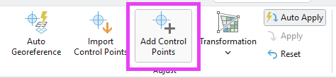
locating the Add Control Point button
Step 1. Access the Add Control Points tool by clicking within the Georeference Menu. The cursor, when hovering over the map image, is now a crosshair shape and will say “From point (source)”.
Step 2. Choose a location on the raster image layer that you can readily identify and “match” within the reference layer. When you have chosen your first location, click on the raster image (at that location) as precisely as possible. (It is usually useful to zoom in.) Selecting distinct features, like the intersection of lines, may help improve the accuracy of your control points as they can enable greater precision and are easy to reference in the vector layer.
placing your control points on the raster layer
Step 3. The next step will specify the coordinates for this control point within the raster. In effect, we are telling the software to move the location of the raster control point to the coordinates of the map view, using the vector layer as a reference. (In other words, we want to connect the location of our raster’s control point to the corresponding location on our vector layer.) To do this, click on the appropriate location using your vector layer (on your map canvas) as reference. Since we’ve selected a location on the raster layer, the crosshair will now say “To point (target).”
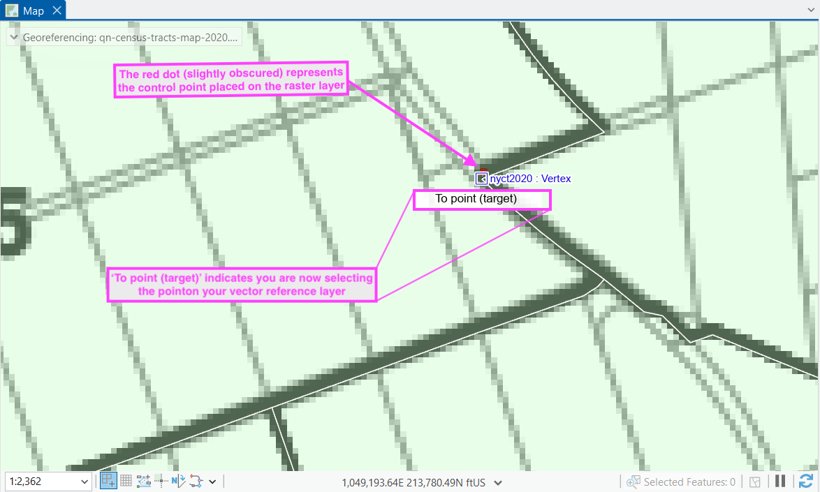
placing your control points using the vector reference layer
A new control point is successfully placed when two crosshairs (one red and one green) appear on your map canvas. You can also check the information about individual control points by clicking Control Point Table in the Georeference Menu.
view after placing both control points
Repeat. The first control point will give a single point of placement information to the raster. Adding more control points (minimum of three) will stretch and scale the image to match the coordinates of the map canvas. Repeat the process of adding control points until you have an adequate number and are satisfied with the results. See Notes on Control Points at the end of this tutorial for more tips.
Checking Accuracy and Adjusting Control Points
The control points we have added do not permanently change the raster image. These “connections” between the raster’s cells and the map canvas are saved only within this map project. This gives us the ability to make changes and adjustments before creating a new georeferenced raster dataset from our results.
Residual Values
After adding control points (but before running the georeference operation/transformation), check the accuracy of the control points. Locational information for each control point is listed in the Control Point Table. Each row represents a control point; the columns list coordinate information related to each control point (source, destination, and difference in locations).
The final column of the table, Residual, indicates the error between an estimated and an actual location for a control point. In other words, these residuals are the distance between the control point’s location on the raster and the corresponding coordinates on the map view. The closer the number is to zero, the more accurate the location of the control point. With three control points or fewer, the residuals will be zero (because three points determine a plane). Starting with the fourth control point (for most transformation types, noted below), locations will be stretched or pulled to minimize the residuals across all control points. You may notice residual values changing as you add control points.
the Control Point Table with residual information highlighted
The Map View also provides this information visually: if you zoom in very closely to a given control point, you will see a black line indicating the residual distance (and the direction of this “pulling”).
checking control point accuracy using visual cue
Deleting and Editing Control Points
To remove a control point, open the Control Point Table and select the control point you wish to remove. Then click Delete on the Georeference Menu or from within the Control Point Table.
locating the Delete Control Point button (in the Georeference Menu)
locating the Delete Control Point button (in the Control Point Table)
To adjust the location of your control point, open the Control Point Table and select the control point you wish to adjust. You can automatically zoom in on your selected control point by double clicking on the row (to the left of the check-mark) which corresponds to the control point of interest in the Control Point Table You can then click on the crosshairs on your map canvas and drag and drop to reposition them.
Transformation & Output
When you are fully satisfied with your georeferencing, it is time to create a new raster dataset–complete with coordinate information in the chosen CRS–through transformation. To do this, we establish (or confirm) the Transformation Settings then save or export a newly georeferenced raster using these settings.
Transformation
the Transformation Settings button on the Georeference Menu
Click the Transformation button on the to open the dropdown with different transformation options.
The transformation type determines how coordinates are assigned to the raster between the control points. (A description of different transformation types is forthcoming and will be linked here for your reference in the future!) The optimal transformation type will depend on your data and your project needs. For the purposes of this demonstration, a Projective transformation is appropriate.
Saving Your Georeferencing Information
Once you’re satisfied with your control points, it’s time to save your work. You will see three options for saving in the Georeference Menu.
Save will save your georeferencing information with the original source raster file and its auxiliary files.
Save as New will create (export) a new raster file with the georeferencing information.
Export Control Points will save your control points in a .txt file, which can then be imported using Import Control Points in the Georeference Menu.
For this tutorial, we will select Save as New so our original raster file remains in its original format. Once you select Save as New, the Export Raster tool’s dialogue box will open up with export options.
Export Settings
Under the Output Settings, you will specify a name and a location for your output file. The most commonly used settings for exporting a georeferenced raster are detailed below:
Output Raster Dataset: allows you to set a location and name for your raster output
Output Format: you can select your desired file type for your georeferenced raster. For this tutorial, we will leave it as the default, geoTIFF.
Spatial Reference System and Clipping Options: Ensure the coordinate system matches the CRS of your reference layer and map frame. Here you can also select clipping options.
Raster Properties: Here you can specify the cell size of your output raster. These values will adjust based on any settings you change in your spatial reference system and clipping options. You can also manually set them.
NoData value: By default, output cells without data (usually along the edges of the rectangular output) will have null values. Here you can specify a different value.
Resampling Method: You will find the resampling method under the tool’s Settings tab. By default, it is set to Nearest Neighbor which is appropriate for imagery rasters.
the Export Raster tool: General Tab
the Export Raster tool: Settings Tab
More Notes & Tips on Control Points
Where to place control points? While every project is different, there are some general rules of thumb. Disperse control points across your raster map, with a few control points placed near the corners (or edges of the map portion of the image) to set the overall scale and dimensions of the map and a few control points spread across the interior.
How many control points? “More control points” is not the same as “better control points.” The target number of control points needed to georeference your raster data will vary depending on the method of transformation you select within Transformation Settings. If you run the georeference operation and are dissatisfied with the accuracy of your result, you can make adjustments to your control points and transformation settings and rerun the operation until your output meets the quality standards of your project. We will often test several versions, reading the impact on our residual values with different control point locations.